Détecteur de Led : 
Dedicated to the automotive environment.
Grâce à leur faible encombrement, les produits de la gamme FEASA et FINN TEST peuvent être installés en face ou au dessus de la DEL. Le détecteur génère lors d'une émission lumineuse de la DEL une fréquence en Khz qui permet de qualifier la couleur de celle-ci et une tension pour quantifier l'intensité lumineuse de la DEL.
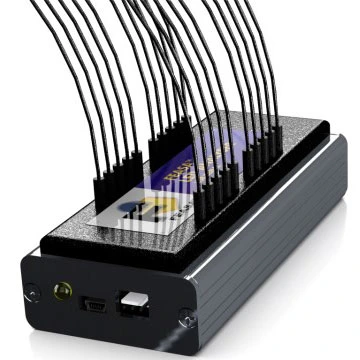
Feasa Automotive LED Headlight Tester
High Brightness LED Analyzer
Specifically designed for testing automotive LED headlights in a production environment.
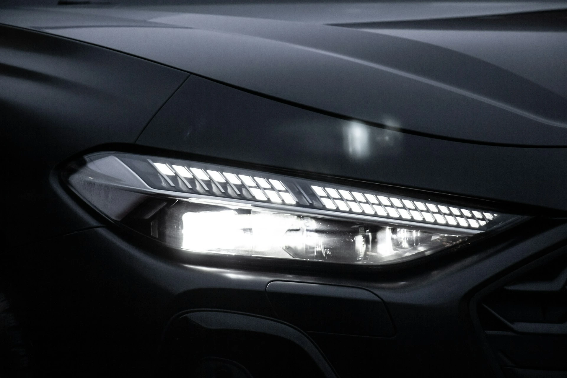
TheFeasa headlight testerwas developed to ensure precise and reliable control of automotive LED headlights directly on production lines. It meets the requirements of modern headlight technologies, including high-brightness LED systems and Matrix headlights.
Measurement Capabilities
LED measurement up to 800 lumens
Individual LED analysis on Matrix modules
Spatial resolution allowing testing of LEDs spaced 1.1 mm center to center
Stable and repeatable measurements under high brightness conditions
Suitable for high-power LEDs used in automotive front headlights
Optical Technology
Optical heads with very low numerical aperture (NA ≈ 0.05)
Reduction of light interference between adjacent LEDs
Excellent optical selectivity for high-density matrices
Optimization for the precise capture of the light flux emitted by each LED
Design adapted to the complex lighting environments of headlight modules
Compatibility and Integration
Designed to work with the Feasa high brightness LED analyzer
Compatible with existing fixture technologies
Easy integration into automated test benches
Suitable for OEM production environments and automotive suppliers
Support for online test architectures or dedicated cells
Interfaces and Communication
The tester supports multiple industrial interfaces to facilitate its integration into existing control systems:
USB
Serial Interface
Daisy Chain for multi-sensor configurations
ICT (In-Circuit Test)
These interfaces allow for fast communication with supervision systems, PLCs, and test software.
Typical Applications
Testing automotive front LED headlights
Control of Matrix LED modules
Validation of optical assembly
Detection of LED brightness, position, or operation defects
Quality control in mass production
Technical Specifications – Feasa Optical Heads
| Parameter | OH10 | OH11 |
|---|---|---|
| Optical head reference | OH10 | OH11 |
| Numerical Aperture (NA) | 0.05 | 0.05 |
| Collection cone angle | 6° | 6° |
| Minimum center-to-center distance | 1.5 mm | 1.1 mm |
| Recommended distance from the LED | 3 mm | 3 mm |
| Drilling hole diameter | 1.00 mm | 0.95 mm |
| Maximum luminous flux per channel | 800 lumens | 800 lumens |
| Minimum luminous flux per channel | 1.0 lumen | 1.0 lumen |
| Optical selectivity | Very high | Very high |
| Typical application | High brightness LED | High density matrix LED |
Functional Versions (FB)
| Analyzer Model | Number of Channels |
|---|---|
| 3FB | 3 channels |
| 5FB | 5 channels |
| 10FB | 10 channels |
| 20FB | 20 channels |
ICT Versions (IB)
| Analyzer Model | Number of Channels |
|---|---|
| 3IB | 3 channels |
| 5IB | 5 channels |
| 10IB | 10 channels |
| 20IB | 20 channels |
Automotive Display Tester
Screen Analyzer – Automotive
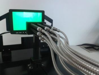
The Feasa Screen Analyzer is a dedicated solution for testing automotive flat screens in an industrial environment. It allows precise control of the photometric performance of displays used in dashboards, infotainment systems, central screens, and head-up displays.
The system is designed to reliably measure the luminance and chromaticity of displays, ensuring compliance with the strict requirements of the automotive industry.
Measurement Functions
Measurement of display luminance
Measurement of chromaticity (color)
Suitable for LCD, TFT, and other automotive display technologies
High repeatability of measurements in production
System Architecture
The Feasa Display Analyzer consists of:
Optical detection heads
Fiber optic cords (Fiber Patch Cords)
Multichannel measurement module
Each analysis module supports up to 6 measurement channels, allowing simultaneous testing of multiple areas of the same display or multiple displays.
Extension and Modularity
Ability to connect multiple modules in Daisy Chain
Simple extension of the total number of channels
Suitable for multi-display test benches or high-speed production lines
Calibration
Two calibration methods are available:
Calibration in the fixture using the Feasa spectrometer and a luminance head
Calibration from a validated reference display, recognized as compliant
These options ensure high measurement accuracy and long-term stability.
Communication Interfaces
USB
Serial
These interfaces ensure simple integration with test systems, monitoring software, and industrial automation.
Typical Applications
Testing automotive displays in production
Quality control of display modules
Validation of colors and brightness
Functional tests at the end of the line
OEM environments and automotive suppliers
Feasa Screen Analyzer
Tested Parameters
| Parameter | Specification |
|---|---|
| Maximum luminance | 10,000 cd/m² |
| Minimum luminance | 0.01 cd/m² |
| Contrast ratio | 200,000 : 1 |
| Display uniformity | cd/m² |
| Chromaticity | x, y |
Measurement Accuracy
(RGB backlight @ x = 0.333 / y = 0.333)
| Parameter | Value |
|---|---|
| Luminance accuracy | < 15 %(±4 % Illuminant A) |
| Chromaticity accuracy (xy) | ±0.01(±0.006 Illuminant A) |
Repeatability
| Parameter | Value |
|---|---|
| Chromaticity xy | ±0.0030 |
| Intensity | < 1 % |
Electrical Characteristics
| Parameter | Specification |
|---|---|
| Power Supply | USB |
| Consumed current | 60 mA |
| Interfaces | Serial, RS232, Daisy Chain |
Physical Characteristics
| Parameter | Specification |
|---|---|
| Dimensions | 124 × 57 × 75 mm |
| Optical fiber length | 0.6 m |
| Fiber diameter | 5.2 mm(sheath included) |
| Minimum bend radius | 25 mm |
| Operating temperature | 0 °C to +40 °C |
Software
| Functionality | Availability |
|---|---|
| Graphical User Interface (GUI) | Yes |
| Command line interface | Yes |
| C / C++ applications | Yes (examples provided) |
| DLL | Yes |
| LabVIEW® support | Yes |
| Product | Reference |
|---|---|
| Feasa Screen Analyzer | Feasa 01-D2, 03-D3, 06-D2 |
| Feasa luminance head | Feasa LU07 |
| Feasa optical fiber cables | Feasa FP05 |
Tester for automotive illuminated switches
Backlit Switches and Controls Analyzer
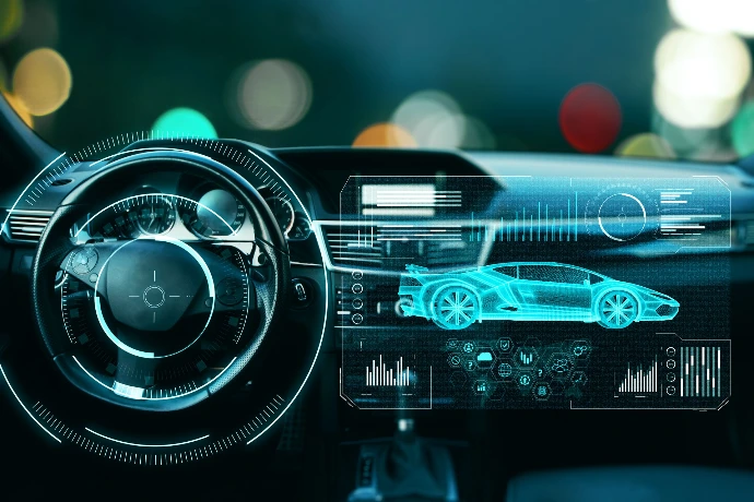
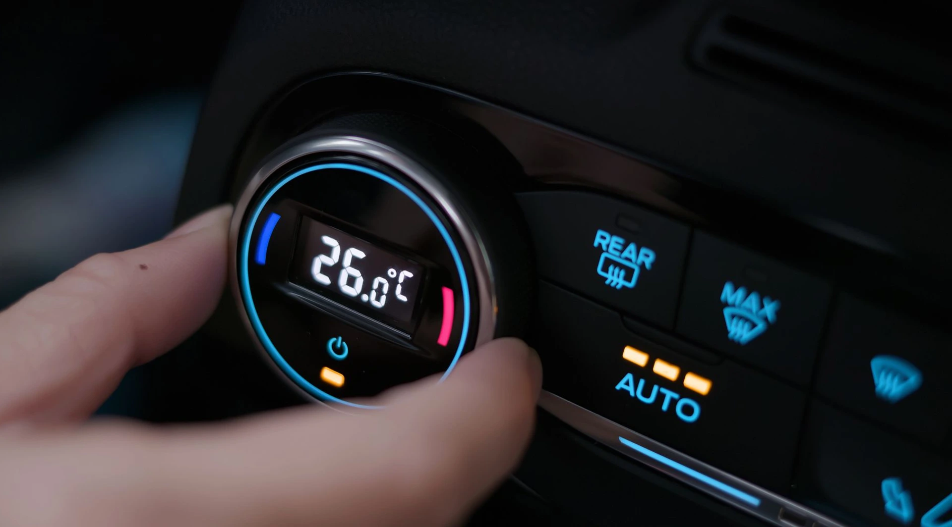
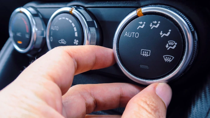
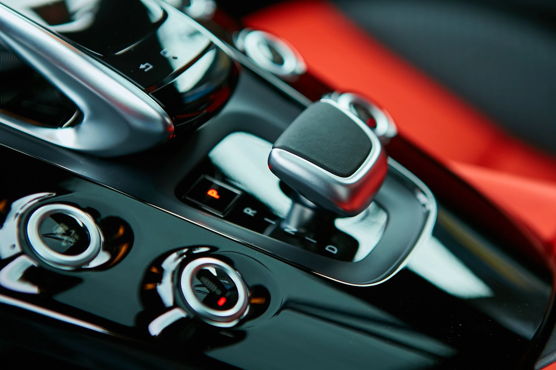
Automakers are increasingly using LED backlit switches and panels to create a cockpit environment that is secure, ergonomic, and aesthetically pleasing. Modern steering wheels now incorporate an increasing number of controls dedicated to infotainment, telephony, and cruise control, enhancing both driver safety and comfort.
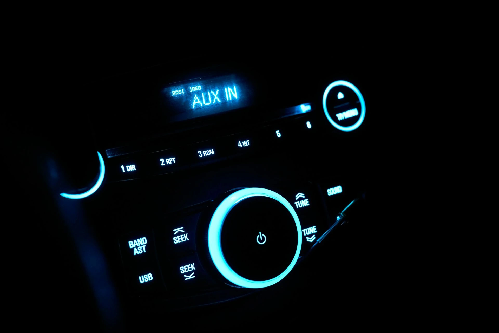
Panels and switches featuring engraved or painted symbols, backlit by LEDs, are generally nearly invisible in daylight, but provide the driver with better visual orientation and spatial perception during nighttime driving.
Production and Quality Challenges
Automotive cockpit subassemblies are often supplied by different manufacturers. It is therefore essential to ensure:
strict tolerances,
standardized test configurations,
perfect color matching,
and uniform light intensity between the different modules.
These requirements are essential to avoid any perception of color or brightness non-uniformity by the end user, which could harm the perceived quality of the vehicle.
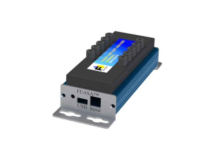
Feasa Solution – Low Light LED Analyzer
The Feasa Low Light LED Analyzer is the ideal solution for these applications. Its increased sensitivity allows for accurate measurement of very low light levels, particularly after light passes through engraved or diffusing plastic materials.
Measured Parameters
The system allows for precise testing of:
Light intensity
Homogeneity of parts
Chromaticity (xy)
Dominant wavelength
Correlated color temperature (CCT)
Key Benefits
Fast and repeatable measurements
High precision at low light levels
Suitable for automotive production environments
Reliability and performance compliant with Feasa LED test solution standards
Feasa Low Light LED Analyzer
Accuracy
| Parameter | Specification |
|---|---|
| Chromaticity xy | ±0.01@ x = 0.33 ; y = 0.33¹ |
¹Value measured immediately after calibration using a known reference source.
Optical Characteristics
| Parameter | Value |
|---|---|
| Minimum luminance | < 0.5 cd/m² |
| Maximum luminance | < 1,000,000 cd/m² |
Repeatability
| Parameter | Value |
|---|---|
| Chromaticity xy | ±0.002 |
| Intensity | < 1 % |
Electrical Characteristics
| Parameter | Specification |
|---|---|
| Power Supply | USB –5 V |
| Current consumption | 80 mA |
| Interfaces | Serial, RS232, Daisy Chain |
Physical Characteristics
| Parameter | Specification |
|---|---|
| Dimensions (3, 5, 6 channels) | 104.5 × 54 × 41 mm(L × W × H)* |
| Dimensions (10 channels) | 45 × 54 × 41 mm(L × W × H)* |
| Optical fiber length | 600 mm |
| Fiber diameter | 2.2 mm ODwithsingle core 1.5 mm |
| Minimum bend radius | 30 mm |
| Operating temperature | 0 °C to +50 °C |
* Dimensions excluding fiber bend radius.
Software
| Functionality | Availability |
|---|---|
| Graphical User Interface (GUI) | Yes |
| Command line interface | Yes |
| C / C++ applications | Yes (examples provided) |
| DLL | Yes |
| LabVIEW® support | Yes |
| Product | Reference |
|---|---|
| Low light LED analyzer – 3 channels | Feasa 3A |
| Low light LED analyzer – 5 channels | Feasa 5A |
| Low light LED analyzer – 6 channels | Feasa 6A |
| Low light LED analyzer – 10 channels | Feasa 10A |
Our trusted partner
We are in good company.

France
Une collaboration depuis 2024